
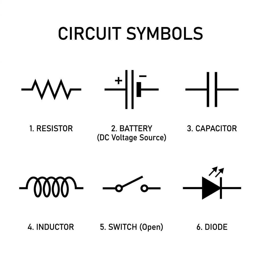
Circuit symbols are simple graphical representations of electrical and electronic components used in circuit diagrams and schematic drawings. Instead of drawing the physical shape of a resistor, capacitor, diode, battery, switch, or transistor, engineers use a recognized symbol to show the component and its role in the circuit.
If you are learning electronics, repairing equipment, studying electrical engineering, or simply trying to understand a schematic, knowing circuit symbols is essential. Once you recognize the most common symbols, you can understand how components connect without needing to see the actual physical device.
There are many types of circuit symbols, including symbols for passive components, power sources, semiconductors, switches, protective devices, motors, transformers, measurement equipment, logic gates, and connections.
The International Electrotechnical Commission (IEC) maintains IEC 60617, the international database for graphical symbols used in electrotechnical diagrams. Its coverage includes conductors, passive components, semiconductors, electrical energy production and conversion, protective devices, measuring instruments, lamps, signaling devices, logic elements, and other diagram symbols.
What Are Circuit Symbols?
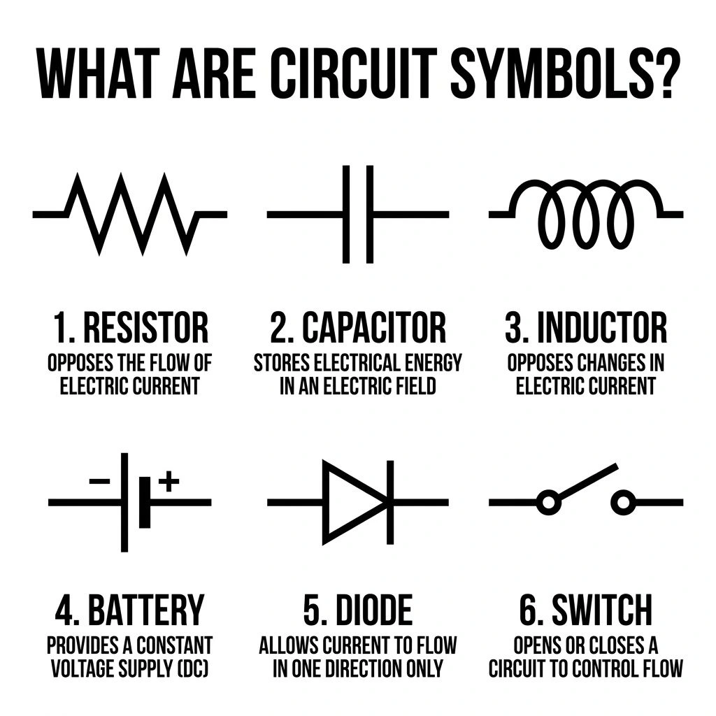
Circuit symbols are standardized or commonly accepted drawings that represent components and functions in an electrical or electronic circuit.
A real resistor might be a small physical component with colored bands or printed markings. In a schematic, however, it may be represented by a simple rectangle or zigzag line.
The purpose is to show what the component does and how it connects, rather than what it physically looks like.
For example:
- A resistor symbol represents resistance.
- A capacitor symbol represents a device that stores electrical charge.
- A diode symbol identifies a semiconductor device with directional behavior.
- A battery symbol represents an electrical source.
- A switch symbol shows a controllable connection.
- A ground symbol identifies a reference or grounding connection.
- A transistor symbol represents a semiconductor device used for switching or amplification.
A schematic is therefore an abstract representation. The physical arrangement of components may look completely different from the arrangement of symbols on the page. Analog Devices notes that schematic diagrams use abstract graphical symbols rather than realistic pictures of components.
Circuit Symbols Quick Reference
The following table gives you a beginner-friendly overview of common circuit symbols and their functions.
| Component | Common Symbol Form | Main Function | Typical Terminals |
| Resistor | Rectangle or zigzag | Limits electrical current | 2 |
| Variable resistor | Resistor with adjustment arrow | Changes resistance | 2–3 |
| Capacitor | Two plates | Stores electrical charge | 2 |
| Polarized capacitor | Capacitor with polarity marking | Stores charge with polarity | 2 |
| Inductor | Coil | Stores energy in a magnetic field | 2 |
| Battery | Long/short parallel lines | Supplies DC energy | 2 |
| Cell | Long/short line pair | Basic electrical source | 2 |
| Diode | Diode shape with cathode bar | Controls current direction | 2 |
| LED | Diode with outward arrows | Produces light | 2 |
| Photodiode | Diode with inward arrows | Detects light | 2 |
| Transistor | Three-terminal semiconductor symbol | Switching/amplification | 3 |
| MOSFET | Gate, drain, source symbol | Electronic switching | 3+ |
| Switch | Movable contact | Opens/closes a circuit | 2+ |
| Fuse | Protective element | Overcurrent protection | 2 |
| Circuit breaker | Switching/protection symbol | Opens circuit during fault | 2+ |
| Transformer | Two coils | Transfers energy magnetically | Multiple |
| Motor | Circle with M | Converts electrical energy to motion | 2+ |
| Lamp | Circle/lamp symbol | Produces light | 2 |
| Relay | Coil and contacts | Electrically controlled switching | Multiple |
| Ammeter | Meter marked A | Measures current | 2 |
| Voltmeter | Meter marked V | Measures voltage | 2 |
| Ground | Grounding/reference symbol | Defines electrical reference | Depends |
| Op-amp | Triangle | Amplifies voltage difference | Multiple |
| AND gate | Logic-gate shape | Logical AND operation | Multiple |
| OR gate | Logic-gate shape | Logical OR operation | Multiple |
| NOT gate | Triangle with inversion bubble | Inverts logic | 2+ |
The exact graphical form can depend on the applicable standard and drafting convention. IEC 60617 is the official IEC database for graphical symbols used in electrotechnical diagrams and includes a large collection of standardized symbols.
Why Are Circuit Symbols Important?
Circuit symbols make complicated electrical information easier to communicate.
Imagine trying to draw the actual physical shape of every resistor, transistor, capacitor, relay, and integrated circuit in a large schematic. The diagram would quickly become difficult to read.
Symbols solve this problem by reducing components to recognizable graphical forms.
They are important for:
- Circuit design
- Electrical engineering
- Electronics education
- Troubleshooting
- Equipment repair
- PCB design
- Electrical installation documentation
- Manufacturing
- Testing
- Technical manuals
- Circuit simulation
- Schematic creation
Standardized symbols are particularly useful when circuit documentation is shared between engineers, technicians, manufacturers, and maintenance teams.
IEC 60617 specifically provides graphical symbols for electrotechnical diagrams across areas such as conductors, passive components, semiconductor devices, energy conversion, protection, measurement, signaling, and logic.
Circuit Symbols vs. Electrical and Electronic Symbols
The terms circuit symbols, electrical symbols, electronic symbols, and schematic symbols are closely related, but they are not always used in exactly the same way.
Circuit Symbols
This is the broad term for symbols used to represent components and functions in circuit diagrams.
Electrical Symbols
Electrical symbols often refer to components and devices used in electrical power, wiring, control, and installation systems.
Examples include:
- Circuit breakers
- Transformers
- Motors
- Generators
- Switches
- Fuses
- Lamps
- Grounding connections
Electronic Symbols
Electronic symbols usually refer to components commonly found in electronic circuits.
Examples include:
- Resistors
- Capacitors
- Diodes
- Transistors
- MOSFETs
- Op-amps
- Integrated circuits
- Logic gates
Schematic Symbols
A schematic symbol is the graphical representation used inside a schematic diagram.
The terms overlap considerably, so you may see them used interchangeably in educational materials.
Resistor Symbols
A resistor is one of the most common components in electrical and electronic circuits.
Its primary purpose is to provide resistance and control electrical current or voltage.
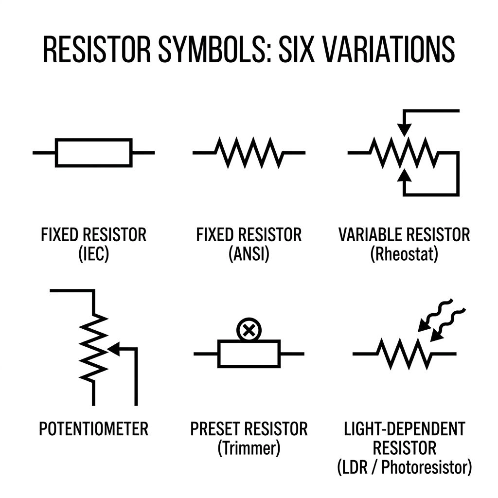
Two common resistor representations are encountered:
- A rectangle, commonly associated with IEC-style diagrams.
- A zigzag line, commonly associated with ANSI-style or North American drafting conventions.
Both can represent the same basic component.
What Does a Resistor Do?
A resistor can be used to:
- Limit current
- Divide voltage
- Set bias conditions
- Protect components
- Control signal levels
- Dissipate electrical energy
The resistance is measured in ohms (Ω).
Variable Resistor Symbol
A variable resistor allows resistance to be adjusted.
Depending on the component, the symbol may show an arrow or other adjustment indication.
Common examples include:
- Potentiometers
- Rheostats
- Trimmers
A potentiometer commonly has three terminals and can be used as an adjustable voltage divider.
Capacitor Symbols
A capacitor stores electrical charge and is widely used in electronic and electrical circuits.
The basic capacitor symbol consists of two conductive plates separated by a gap.
Capacitors are commonly used for:
- Filtering
- Smoothing
- Coupling
- Decoupling
- Timing
- Energy storage
- Noise reduction
Polarized Capacitor Symbol
Some capacitors are polarized, meaning they have designated positive and negative terminals.
A polarized capacitor symbol includes a polarity indication according to the relevant drafting convention.
When using a polarized capacitor, connecting it incorrectly can damage the component or create a safety problem.
Inductor Symbols
An inductor is commonly shown using a series of curved loops representing a coil.
An inductor stores energy in a magnetic field.
Inductors are found in:
- Power supplies
- Filters
- Oscillators
- Radio-frequency circuits
- Energy converters
- Transformers and magnetic systems
Inductors are normally measured in henries (H).
Battery and Cell Symbols
A battery symbol usually consists of alternating long and short parallel lines.
A single cell can be represented by one pair of long and short lines, while multiple cells can be shown together.
Battery symbols are used to represent sources of DC electrical energy.
You may encounter them in:
- Portable electronics
- Automotive circuits
- Battery-management systems
- Toys
- Educational circuits
- Backup systems
A schematic symbol represents the electrical function of the source, not the physical shape of the battery.
Power Source Symbols
Not every circuit gets its power from a battery.
Schematics can also represent:
- DC voltage sources
- AC voltage sources
- Power supplies
- Controlled voltage sources
- Controlled current sources
- Generators
Independent voltage and current sources are commonly represented using dedicated schematic symbols. Analog Devices also notes that independent sources are commonly represented with circular symbols, while controlled sources use diamond-shaped symbols in common schematic conventions.
VCC, VDD, VSS, and GND
Electronic schematics often use labels instead of repeatedly drawing a complete power-source symbol.
Common labels include:
- VCC — commonly used for a positive supply rail
- VDD — commonly used for a supply associated with certain transistor technologies
- VSS — commonly used for a lower or negative supply/reference
- GND — ground or circuit reference
The exact meaning of a supply label depends on the circuit and design convention.
Ground Symbols
Ground is one of the most frequently misunderstood concepts in circuit diagrams.
A ground symbol identifies a reference or grounding connection, but not every ground symbol necessarily means a physical connection to earth.
Different designs may distinguish between:
- Earth ground
- Chassis ground
- Signal ground
- Circuit common
- Analog ground
- Digital ground
Always check the schematic’s labels and documentation.
Why Ground Matters
Ground can provide:
- A voltage reference
- A return path
- A connection to protective earth
- A common reference between circuit sections
- A chassis connection
Never assume that two differently labeled ground connections are automatically interchangeable.
Diode Symbols
A diode is a two-terminal semiconductor device with directional electrical behavior.
The two terminals are:
- Anode
- Cathode
The diode symbol identifies the cathode with a bar.
Diodes are commonly used for:
- Rectification
- Reverse-polarity protection
- Signal processing
- Clamping
- Switching
- Voltage regulation in specialized forms
Analog Devices describes the diode as a two-terminal device commonly used for one-directional current behavior, while also noting that this description is a simplified model.
Diode Polarity
Diodes are polarized.
The positive terminal is the anode, and the negative terminal is the cathode under the usual forward-bias terminology. The cathode corresponds to the bar shown in the standard diode symbol.
This is why diode orientation matters when reading or building a circuit.
LED Symbol
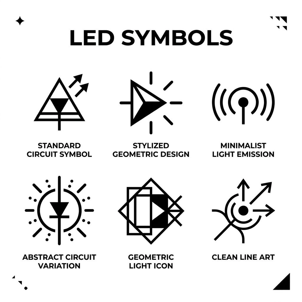
An LED is a light-emitting diode.
Its schematic symbol is based on the diode symbol with arrows pointing outward to indicate emitted light.
LEDs are commonly used for:
- Indicator lights
- Displays
- Status signals
- Lighting
- Optical applications
- Automotive electronics
LED Polarity
An LED is polarized, so its orientation matters.
A typical LED circuit also uses a current-limiting component, commonly a resistor, depending on the design.
Photodiode Symbol
A photodiode is designed to respond to light.
Its symbol is based on the diode symbol but uses arrows directed toward the device to indicate incoming light.
This helps distinguish it from an LED:
- LED: arrows point outward.
- Photodiode: arrows point inward.
Photodiodes are used in:
- Light sensors
- Optical communication
- Measurement systems
- Automatic controls
- Detection circuits
Zener Diode Symbol
A Zener diode is a specialized diode commonly used in voltage-regulation and voltage-clamping applications.
Its symbol resembles a diode but has a modified cathode line.
The symbol helps distinguish it from a standard diode.
Transistor Symbols
Transistors are semiconductor devices widely used as switches and amplifiers.
Two common bipolar transistor types are:
- NPN
- PNP
A bipolar transistor normally has three main terminals:
- Base
- Collector
- Emitter
NPN Transistor Symbol
The NPN symbol has an emitter arrow pointing outward.
A common memory aid is:
NPN — Not Pointing iN.
PNP Transistor Symbol
The PNP symbol has the emitter arrow pointing inward.
The orientation of the transistor symbol is important when interpreting the circuit.
MOSFET Symbols
MOSFET stands for metal-oxide-semiconductor field-effect transistor.
A MOSFET is commonly used as an electrically controlled switch and can also be used in amplification and other applications.
Important terminals include:
- Gate
- Drain
- Source
Common types include:
- N-channel MOSFET
- P-channel MOSFET
MOSFET symbols contain more information than simply “this is a transistor,” so beginners should learn to identify the gate, source, and drain connections.
Switch Symbols
A switch controls an electrical connection.
A basic switch symbol shows contacts that can open or close.
Switches can be used to:
- Turn equipment on or off
- Select between circuit paths
- Control motors
- Trigger electronic circuits
- Control lighting
- Provide safety functions
Normally Open Switch
A normally open, or NO, contact is open in its normal state.
When activated, it closes.
Normally Closed Switch
A normally closed, or NC, contact is closed in its normal state.
When activated, it opens.
This distinction is especially important in control systems.
Relay Symbols
A relay is an electrically controlled switching device.
A relay schematic normally separates the idea of the coil from the contacts.
When current is applied to the coil, the magnetic mechanism changes the state of the contacts.
Relays are commonly used in:
- Automotive systems
- Industrial control
- Automation
- Protection systems
- Motor control
- Electrical switching
When reading a relay diagram, identify both the coil and the associated contacts.
Fuse Symbols
A fuse is a protective device designed to interrupt a circuit when excessive current causes the fuse element to operate.
Fuses are commonly used in:
- Power supplies
- Automotive systems
- Electrical panels
- Electronic devices
- Industrial equipment
The fuse symbol helps you identify the protective portion of a circuit.
Circuit Breaker Symbols
A circuit breaker is another protective device.
Unlike a conventional fuse, a circuit breaker can generally be reset after it interrupts a fault, depending on its design.
Circuit-breaker symbols can appear in:
- Distribution systems
- Electrical panels
- Industrial diagrams
- Building electrical plans
- Protection circuits
The symbol indicates that the device can interrupt the circuit under specified conditions.
Transformer Symbols
A transformer transfers electrical energy between circuits through magnetic coupling.
Its schematic representation typically contains two coil sections and may include core lines.
Transformers are used for:
- Voltage conversion
- Electrical isolation
- Power supplies
- Audio applications
- Distribution systems
- Signal coupling
IEC’s graphical-symbol coverage includes transformers, machines, reactors, power converters, primary cells, accumulators, and power generators.
Motor Symbols
A motor converts electrical energy into mechanical motion.
A common motor symbol is a circle containing M.
Motors are used in:
- Fans
- Pumps
- Robotics
- Machinery
- Vehicles
- Industrial automation
- Household appliances
The symbol tells you that the circuit is connected to a mechanical load.
Generator Symbols
A generator converts mechanical energy into electrical energy.
Generator symbols are commonly encountered in:
- Power-system diagrams
- Electrical generation systems
- Industrial equipment
- Backup power systems
- Renewable-energy diagrams
The exact symbol depends on the generator type and diagram convention.
Lamp and Light Symbols
A lamp symbol represents a device that produces light.
It may appear in:
- Lighting diagrams
- Control circuits
- Indicator circuits
- Automotive systems
- Electrical installation plans
A lamp symbol should not automatically be assumed to represent a specific physical bulb type unless the diagram identifies it.
Speaker and Buzzer Symbols
Audio-output components also have schematic symbols.
A speaker converts electrical signals into sound.
A buzzer produces an audible alert.
They may appear in:
- Alarm circuits
- Audio equipment
- Doorbells
- Electronic projects
- Warning systems
Measurement Symbols
Measurement devices are commonly represented by a circle containing an identifying letter or marking.
Voltmeter Symbol
A voltmeter measures voltage.
It is commonly represented by a circle containing V.
Ammeter Symbol
An ammeter measures electrical current.
It is commonly represented by a circle containing A.
Ohmmeter
An ohmmeter measures resistance.
Depending on the diagram convention, measurement symbols may vary, so the surrounding labels should always be considered.
Op-Amp Symbol
An operational amplifier, or op-amp, is commonly represented by a triangle.
A basic op-amp has:
- Non-inverting input
- Inverting input
- Output
Many real op-amps also have power connections.
Op-amps are used in:
- Amplifiers
- Filters
- Comparators
- Sensor circuits
- Signal conditioning
- Analog processing
A triangle in a circuit diagram does not automatically mean “diode.” The terminals and labels tell you what the symbol represents.
Logic Gate Symbols
Digital circuits use graphical symbols to represent logical operations.
Common logic gates include:
- AND
- OR
- NOT
- NAND
- NOR
- XOR
- XNOR
IEC’s graphical-symbol system covers binary logic elements and related functions.
AND Gate
An AND gate produces an active output only when its required inputs satisfy the AND condition.
The traditional symbol has a distinctive curved output side and flatter input side.
OR Gate
An OR gate produces an active output when one or more inputs satisfy the OR condition.
Its traditional shape has a curved input side.
NOT Gate
A NOT gate inverts a logic signal.
A small circle, called a bubble, at the output indicates inversion.
NAND Gate
A NAND gate is an AND function followed by inversion.
It is commonly represented as an AND gate with an output bubble.
NOR Gate
A NOR gate is an OR function followed by inversion.
It is represented as an OR gate with an output bubble.
XOR Gate
An XOR gate represents exclusive OR behavior.
Its traditional symbol resembles an OR gate with an additional curved line on the input side.
XNOR Gate
An XNOR gate is an XOR function followed by inversion.
It can be recognized as an XOR symbol with an output bubble.
Wire and Connection Symbols
Understanding connections is just as important as recognizing components.
A line in a schematic commonly represents an electrical conductor.
The way lines meet tells you how the circuit is connected.
Wire Junctions
A junction may be represented by a filled dot where conductors meet.
This commonly indicates that the wires are electrically connected.
Crossing Wires
Two lines can cross without necessarily being electrically connected.
The diagram’s convention determines how this should be interpreted.
When in doubt, inspect:
- Junction dots
- Connection points
- Labels
- Net names
- The drawing standard
Terminal Symbols
A terminal represents a connection point where a circuit connects to another circuit, device, cable, or external connection.
Connector Symbols
Connectors allow separate circuit sections or devices to be connected and disconnected.
Connector symbols can appear in:
- Computer hardware
- Industrial controls
- Automotive systems
- Power equipment
- Electronic devices
What Do R1, C1, D1, and Q1 Mean?
Letters and numbers beside circuit symbols are often called reference designators.
They help identify individual components.
Common examples include:
| Designator | Typical Component |
| R | Resistor |
| C | Capacitor |
| L | Inductor |
| D | Diode |
| Q | Transistor |
| U | Integrated circuit |
| F | Fuse |
| S or SW | Switch |
| K | Relay in many conventions |
| T | Transformer in many conventions |
| J | Connector in many conventions |
For example:
- R1 = resistor number 1
- R2 = resistor number 2
- C1 = capacitor number 1
- D1 = diode number 1
- Q1 = transistor number 1
These conventions can vary between industries, standards, and organizations, so the design documentation should be treated as the final authority.
How to Identify an Unknown Circuit Symbol
If you see an unfamiliar symbol, do not guess immediately.
Use a systematic approach.
Look at the Basic Shape
First ask whether the symbol resembles:
- A resistor
- Capacitor
- Coil
- Diode
- Transistor
- Switch
- Transformer
- Logic gate
- Meter
- Power source
The overall shape often gives you the first clue.
Count the Terminals
The number of terminals can narrow down the possibilities.
For example:
- 2 terminals → resistor, capacitor, inductor, diode, fuse
- 3 terminals → transistor, potentiometer, some sensors
- Multiple terminals → relay, IC, connector, transformer, or other multi-terminal device
Terminal count alone is not enough, but it is useful.
Look for Arrows
Arrows can provide important information.
Examples include:
- LED → arrows generally point outward
- Photodiode → arrows point toward the diode
- Transistor → emitter arrow
- Adjustable components → adjustment arrows
- Current or signal arrows → direction or flow indication
Check Polarity Markings
Look for:
- Plus signs
- Minus signs
- Diode bars
- Positive capacitor markings
- Pin labels
Polarity can determine whether a component is connected correctly.
Check the Reference Designator
A nearby label can provide another clue.
For example:
R4 strongly suggests a resistor.
C3 suggests a capacitor.
D5 suggests a diode.
Follow the Wires
Sometimes the surrounding circuit makes the component’s function obvious.
A symbol connected between a power rail and ground may have a different role from the same basic component used in a signal path.
How to Read Circuit Symbols in a Schematic
Learning individual symbols is only the first step.
The real skill is understanding how the symbols work together.
Start With the Power Source
Find:
- Battery
- DC supply
- AC source
- Power rail
- Generator
- Other source
This tells you where the electrical energy originates.
Trace the Connections
Follow the wires and identify junctions.
Do not simply read the schematic from left to right. Circuit diagrams can use layouts that prioritize clarity rather than physical placement.
Analog Devices explains that a schematic’s symbol arrangement does not necessarily resemble the physical arrangement of the components.
Identify Each Component
Label the major components mentally or on paper.
For example:
Source → Switch → Resistor → LED → Return
You can then ask what each component is doing.
Check Direction and Polarity
Pay special attention to:
- Diodes
- LEDs
- Transistors
- Polarized capacitors
- Batteries
- Power sources
Look at Values
A symbol tells you what a component is, but a nearby value tells you more about its characteristics.
Examples:
- 1 kΩ resistor
- 10 µF capacitor
- 5 V supply
- 10 mH inductor
The value can be essential for understanding how the circuit operates.
Simple Circuit Examples
Example 1: Basic LED Circuit
A simple LED circuit may contain:
Battery → Resistor → LED → Return
Each part has a different job:
- Battery supplies energy.
- Resistor limits current.
- LED converts electrical energy into light.
- Return connection completes the circuit.
The resistor is important because an LED should normally be operated with appropriate current control rather than connected directly to an ideal voltage source.
Example 2: Switch-Controlled Lamp
A basic lighting circuit can be understood as:
Power source → Switch → Lamp → Return
The switch controls whether the circuit path is complete.
When the switch closes, the circuit can conduct.
When it opens, the circuit path is interrupted.
Example 3: RC Circuit
An RC circuit contains:
- Resistor
- Capacitor
The resistor controls current and the capacitor stores charge.
Together, they can be used for:
- Timing
- Filtering
- Signal shaping
- Transient response
Example 4: Transistor Switching Circuit
A transistor can be used to control a load.
A simplified arrangement might contain:
Control signal → Transistor → Load
The transistor acts as an electronically controlled switch.
The actual circuit requires appropriate biasing, component selection, and protection based on the application.
IEC vs. ANSI Circuit Symbols
One reason circuit diagrams can confuse beginners is that symbols may not always look identical.
Different standards and drafting traditions can use different graphical conventions.
Resistor Example
One of the most familiar differences is the resistor.
IEC-style convention: commonly uses a rectangular resistor symbol.
ANSI/North American convention: commonly uses a zigzag resistor symbol.
Both can represent a resistor.
The difference does not mean that one is automatically a different component.
Why Do Different Symbols Exist?
Electrical documentation developed through different national and industry conventions.
Today, international standards such as IEC 60617 provide standardized graphical symbols for electrotechnical diagrams, while other conventions may still appear in educational materials, software, older documentation, and particular industries. IEC identifies IEC 60617 as its graphical-symbol database for diagrams.
Which Symbol Should You Use?
Use the standard required by the project, company, institution, software library, or applicable engineering documentation.
Consistency is more important than randomly mixing conventions.
Circuit Symbols for Electrical Protection
Protection symbols are especially important in electrical diagrams.
Common protective devices include:
- Fuses
- Circuit breakers
- Surge-protection devices
- Overcurrent protection
- Thermal protection
- Grounding/protective connections
IEC 60617 specifically covers switchgear, controlgear, and protective devices.
When reading a power schematic, identify protection devices before examining the normal operating path.
Circuit Symbols for Home and Building Wiring
Circuit symbols are not limited to electronics.
Electrical installation diagrams may include symbols for:
- Lamps
- Switches
- Outlets
- Distribution boards
- Circuit breakers
- Fuses
- Motors
- Transformers
- Grounding
- Connections
- Communication equipment
IEC 60617 includes symbols used in architectural and topographical installation plans and diagrams as part of its coverage.
Circuit Symbols for PCB and Electronic Design
Circuit symbols are also important when designing printed circuit boards.
A PCB itself contains physical components and copper traces, while the schematic represents the electrical relationships between those components.
A typical design workflow may involve:
Schematic → Component assignment → PCB layout → Manufacturing files
The schematic symbol therefore provides the logical representation before the physical board layout is created.
Modern schematic tools allow designers to select, rotate, connect, label, and assign components within a schematic environment.
Circuit Symbols for Circuit Simulation
Simulation software also relies on schematic symbols.
A simulator may allow you to place:
- Resistors
- Capacitors
- Inductors
- Diodes
- Transistors
- Voltage sources
- Current sources
- Ground
- Integrated models
The graphical symbol provides the visual interface, while the simulation model defines the component’s electrical behavior.
For example, LTspice provides schematic capture for placing components such as resistors, capacitors, voltage sources, and ground before simulation.
Common Circuit Symbol Mistakes
Mistaking a Diode for an LED
An LED is a type of diode, but its symbol includes outward arrows indicating light emission.
Do not assume every diode symbol represents an LED.
Confusing an LED With a Photodiode
Remember:
- LED → light goes out
- Photodiode → light comes in
Confusing a Resistor With an Inductor
A resistor may be drawn as a rectangle or zigzag.
An inductor is generally represented by coil-like loops.
Ignoring Polarity
Do not ignore polarity markings on:
- Diodes
- LEDs
- Polarized capacitors
- Batteries
- Certain semiconductor devices
Assuming Every Ground Means Earth
A ground symbol can indicate a circuit reference, chassis connection, signal ground, or protective earth depending on the design.
Assuming Crossing Wires Are Connected
Check the diagram’s junction convention.
Confusing an Op-Amp With Other Triangle Symbols
An op-amp is generally shown as a triangle with multiple terminals.
Do not identify a component solely because it contains a triangular shape.
Ignoring Normally Open and Normally Closed Contacts
NO and NC contacts behave differently.
This matters in:
- Relays
- Control systems
- Safety circuits
- Industrial automation
Assuming Every Symbol Is Universal
Symbols can vary according to standards and drafting conventions.
Always consider the standard used by the schematic.
Symbol Orientation vs. Physical Orientation
Another common beginner mistake is assuming that the way a component is drawn on the page tells you exactly how the physical component must be positioned.
A schematic is primarily concerned with electrical relationships.
A resistor drawn vertically does not necessarily mean the physical resistor must stand vertically on the PCB.
However, electrical polarity and terminal identity still matter for directional components.
For example:
- Diode orientation matters.
- LED polarity matters.
- Polarized capacitor polarity matters.
- Transistor terminal identity matters.
The graphical rotation of a non-polarized component is usually a drafting choice rather than a physical installation instruction.
Circuit Symbols Cheat Sheet by Category
Passive Components
Common passive-component symbols include:
- Resistor
- Variable resistor
- Potentiometer
- Capacitor
- Variable capacitor
- Inductor
- Transformer
Semiconductor Components
Common semiconductor symbols include:
- Diode
- LED
- Zener diode
- Schottky diode
- Photodiode
- NPN transistor
- PNP transistor
- MOSFET
- SCR
- TRIAC
Switching Components
Common switching symbols include:
- SPST switch
- SPDT switch
- DPST switch
- DPDT switch
- Push button
- Relay contacts
- Relay coil
Protection Components
Common protection symbols include:
- Fuse
- Circuit breaker
- Overcurrent protection
- Surge protection
- Thermal protection
Power Components
Common power symbols include:
- Cell
- Battery
- AC source
- DC source
- Generator
- Power rails
- Ground
Output Components
Common output symbols include:
- Lamp
- LED
- Motor
- Speaker
- Buzzer
Measurement Components
Common measurement symbols include:
- Ammeter
- Voltmeter
- Ohmmeter
- Other measurement instruments
Digital Components
Common logic symbols include:
- AND
- OR
- NOT
- NAND
- NOR
- XOR
- XNOR
What Makes a Good Circuit Symbol?
A useful circuit symbol should make the component or function understandable without unnecessary detail.
A good schematic symbol generally provides:
- Clear identity
- Recognizable graphical form
- Correct terminals
- Appropriate polarity markings
- Functional indicators where needed
- Consistent orientation
- Relevant labels
The purpose of a schematic is not to make components look realistic. It is to communicate the electrical structure clearly.
Are Circuit Symbols Standardized?
Yes, many circuit symbols are standardized.
The IEC 60617 database is the IEC’s official source for standardized graphical symbols for electrotechnical diagrams. The current database covers a broad range of applications, including conductors, passive components, semiconductor devices, electrical energy production and conversion, protective devices, measuring instruments, signaling devices, installation diagrams, logic elements, and analog or hybrid elements.
However, not every diagram you encounter will use identical-looking symbols.
You may encounter:
- Different national conventions
- Older symbols
- Industry-specific conventions
- Software-specific libraries
- Simplified educational symbols
- Manufacturer-specific representations
For professional work, follow the applicable standard and documentation requirements.
Why Circuit Symbols Do Not Always Look Like Real Components
A circuit symbol is an abstraction.
A real electronic component contains physical details that are usually irrelevant to the schematic.
For example, a physical transistor may be packaged in a tiny plastic or metal case, while its schematic symbol focuses on:
- Electrical terminals
- Control relationship
- Device type
- Directional information
The same principle applies to integrated circuits.
A complicated IC may be represented as a block with labeled pins instead of showing every transistor inside it.
This keeps the schematic readable.
How to Learn Circuit Symbols Faster
You do not need to memorize hundreds of symbols at once.
Start with the most frequently encountered components.
First Learn These
- Wire
- Ground
- Battery
- Resistor
- Capacitor
- Inductor
- Switch
- Diode
- LED
- Transistor
- Fuse
- Motor
- Transformer
- Relay
- Op-amp
Then Learn Specialized Symbols
After that, study:
- MOSFETs
- Zener diodes
- Photodiodes
- Thyristors
- TRIACs
- Logic gates
- Sensors
- Connectors
- Measurement devices
- Power-system symbols
Learn Symbols in Groups
Grouping is easier than memorizing random symbols.
For example:
Passive: resistor, capacitor, inductor
Semiconductor: diode, LED, transistor, MOSFET
Protection: fuse, breaker
Control: switch, relay
Power: battery, source, transformer
This helps you recognize patterns.
Frequently Asked Questions About Circuit Symbols
What are circuit symbols?
Circuit symbols are graphical representations of electrical and electronic components used in schematic diagrams. They show components and their electrical relationships without requiring realistic drawings of the physical devices.
What are the most common circuit symbols?
Common circuit symbols include the resistor, capacitor, inductor, battery, ground, switch, diode, LED, transistor, fuse, transformer, motor, relay, lamp, and measurement symbols.
What is the symbol for a resistor?
A resistor is commonly represented by a rectangle in IEC-style diagrams or a zigzag line in common ANSI/North American conventions. Both can represent a resistor.
What is the symbol for a capacitor?
A basic capacitor is commonly represented by two parallel conductive plates separated by a gap. Polarized capacitor symbols include additional polarity information.
What does a diode symbol mean?
A diode symbol represents a two-terminal semiconductor device with directional behavior. The cathode is identified by the bar in the standard diode symbol.
What is the difference between a diode and an LED symbol?
An LED symbol is based on the diode symbol but includes arrows pointing outward to indicate emitted light. A photodiode uses arrows pointing toward the diode to indicate incoming light.
What does R1 mean on a circuit diagram?
R1 is commonly a reference designator identifying the first resistor in a schematic. Other examples include C1 for a capacitor, D1 for a diode, and Q1 for a transistor.
What does C1 mean on a circuit diagram?
C1 commonly identifies capacitor number one in a schematic. The letter C is widely used as a capacitor reference designator, while the number distinguishes that particular component from other capacitors.
What does D1 mean on a circuit diagram?
D1 commonly identifies the first diode in a schematic. The exact reference-designator conventions can vary between standards and organizations.
What does Q1 mean on a circuit diagram?
Q1 commonly identifies a transistor or transistor-like semiconductor device in many schematic conventions.
Why do circuit symbols look different in different diagrams?
Different standards, regions, industries, software libraries, and drafting traditions can use different graphical conventions. IEC 60617 provides an international reference for graphical symbols used in electrotechnical diagrams.
What is the difference between IEC and ANSI circuit symbols?
IEC and ANSI/North American drafting conventions can represent some components differently. A familiar example is the resistor: IEC-style diagrams commonly use a rectangle, while ANSI-style diagrams commonly use a zigzag representation.
What does a ground symbol mean?
A ground symbol identifies an electrical reference or grounding connection. Its exact meaning depends on the circuit and can refer to signal ground, circuit common, chassis ground, or protective earth.
How do I identify an unknown circuit symbol?
Start by examining its shape, number of terminals, arrows, polarity markings, reference designator, labels, and surrounding connections. Comparing these features with a reliable symbol reference can help identify the component.
Are circuit symbols universal?
No single visual convention should be assumed to be identical in every document. Many symbols are standardized, but variations can occur between standards, regions, industries, software tools, and older documentation.
What is the easiest way to learn circuit symbols?
Start with common components such as resistors, capacitors, inductors, batteries, switches, diodes, LEDs, transistors, fuses, transformers, and ground. Then practice reading simple schematics rather than memorizing symbols in isolation.
Can circuit symbols tell me how a component works?
They provide important information about the component type, terminals, polarity, direction, or function, but the symbol alone does not provide every electrical specification. Component values, ratings, datasheets, and surrounding circuitry may also be required.
Are circuit symbols used in PCB design?
Yes. PCB design commonly begins with a schematic in which circuit symbols represent the electrical components and connections. The physical PCB layout then translates those logical connections into component footprints and conductive paths.
Conclusion
Circuit symbols are the visual language used to represent electrical and electronic components in schematic diagrams. They allow engineers, students, technicians, and hobbyists to understand a circuit without drawing every component as it physically appears.
The most important symbols to learn first are the resistor, capacitor, inductor, battery, ground, switch, diode, LED, transistor, fuse, transformer, motor, relay, and power-source symbols.
Once you understand these basics, you can move on to MOSFETs, specialized diodes, logic gates, op-amps, connectors, measurement devices, and more advanced electrical symbols.
Remember that symbols can vary between standards and drafting conventions. IEC 60617 provides the IEC’s standardized graphical-symbol database for electrotechnical diagrams and covers a wide range of electrical, electronic, control, protection, measurement, and logic applications.
The most effective way to learn is not simply to memorize a list. Study each symbol together with its name, function, terminals, polarity, reference designator, and typical use. Then practice identifying those symbols inside simple circuit diagrams.
Once you can look at a schematic and quickly recognize the components and connections, reading more complicated circuits becomes much easier.

Elliot Kensington
Elliot Kensington is a storyteller at heart, always fascinated by the hidden corners of human imagination. From a young age, he found comfort in books and the worlds they created, inspiring him to craft tales that blend emotion, suspense, and wonder. His writing journey began with short stories that captured fleeting moments of life, and over time, evolved into novels that explore both the extraordinary and the everyday. Elliot believes that every story holds a piece of the soul, and his mission is to connect readers to those moments that linger long after the last page. When he’s not writing, he enjoys exploring nature, capturing moments through photography, and seeking inspiration in the little things.
Books by Elliot Kensington:
-
Shadows of Tomorrow
-
The Whispering Path