
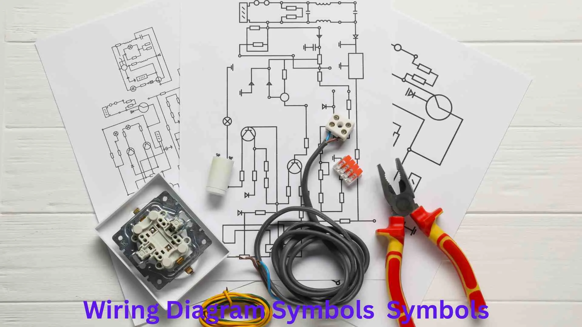
Wiring diagram symbols are the standard visual signs used to represent electrical components and connections in a circuit.
In simple terms, these symbols act like a universal language for electricians, engineers, technicians, students, and DIY enthusiasts.
Understanding wiring diagram symbols makes it easier to read electrical plans, troubleshoot problems, and safely install electrical systems.
Whether you’re learning basic electronics, studying electrical engineering, working on home wiring projects, or maintaining industrial equipment, knowing these symbols is an essential skill.
This guide explains the most common wiring diagram symbols, their meanings, practical applications, and why they matter in today’s technology-driven world.
What Are Wiring Diagram Symbols?
Wiring diagram symbols are graphical representations of electrical and electronic components used in circuit diagrams and wiring plans.
Instead of drawing actual components, designers use standardized symbols to make diagrams easier to read and understand.
For example:
- A battery is shown using parallel lines.
- A switch has a simple line-based symbol.
- A resistor appears as a zigzag or rectangular shape.
- A lamp has a circular symbol with markings inside.
These symbols allow engineers and electricians worldwide to understand the same diagram regardless of language differences.
Why Are Wiring Diagram Symbols Important?
Imagine trying to build a complex electrical system without symbols. Every diagram would be large, confusing, and difficult to understand.
Wiring diagram symbols provide:
- Clear communication
- Faster troubleshooting
- Improved safety
- Standardized documentation
- Easier maintenance
- Better training and education
They help everyone involved in electrical work understand exactly how a system is designed.
A Brief History of Wiring Diagram Symbols
Electrical symbols have evolved alongside the development of electricity itself.
During the late 1800s, inventors such as Thomas Edison and Nikola Tesla contributed to the rapid growth of electrical technology.
As electrical systems became more complex, engineers needed standardized methods to communicate designs.
Organizations eventually developed universal standards to ensure consistency in electrical drawings worldwide.
Today, standards are maintained by organizations such as:
- Institute of Electrical and Electronics Engineers
- International Electrotechnical Commission
- National Electrical Manufacturers Association
How Wiring Diagram Symbols Work
Every symbol represents a specific component or electrical function.
When combined, these symbols create a complete picture of how electricity flows through a system.
Think of them as words in a sentence:
- Components = Words
- Connections = Grammar
- Diagram = Complete Story
A skilled electrician can look at a wiring diagram and immediately understand how a circuit operates.
Basic Wiring Diagram Symbols
Wire Symbol
The wire is one of the most common symbols.
Purpose
Represents electrical conductors carrying current between components.
Symbol Meaning
A simple straight line typically represents a wire connection.
Applications
- Home wiring
- Industrial control systems
- Automotive circuits
- Electronics
Connected Wires Symbol
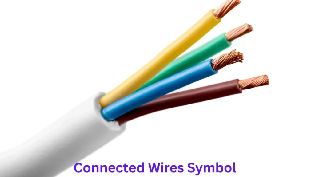
When wires join together, a dot is often placed at the intersection.
Meaning
The dot indicates an electrical connection.
Example
In a lighting circuit, multiple wires may connect at a junction box.
Crossing Wires Symbol
Sometimes wires cross without connecting.
Meaning
Crossing lines without a dot usually indicate no electrical connection.
This distinction helps prevent wiring mistakes.
Power Source Symbols
Battery Symbol
The battery symbol consists of long and short parallel lines.
Meaning
Represents stored electrical energy.
Common Uses
- Flashlights
- Cars
- Electronic devices
- Backup systems
DC Power Supply Symbol
DC stands for Direct Current.
Applications
- Mobile phones
- Computers
- Solar systems
- Electronic circuits
AC Power Supply Symbol
AC stands for Alternating Current.
Applications
- Household electricity
- Industrial equipment
- Commercial buildings
Most homes receive AC power from the electrical grid.
Switch Symbols
Switches control the flow of electricity.
Single-Pole Switch
This is the most common switch symbol.
Use
Turns a circuit on or off.
Examples
- Room lights
- Fans
- Appliances
Double-Pole Switch

Controls two circuits simultaneously.
Applications
- Water heaters
- Large equipment
- Industrial machinery
Push Button Switch
Used when temporary activation is needed.
Examples
- Doorbells
- Elevator controls
- Industrial machines
Protection Device Symbols
Protection devices help prevent electrical accidents.
Fuse Symbol
A fuse protects circuits from excessive current.
Function
The fuse melts when current exceeds safe limits.
Benefits
- Fire prevention
- Equipment protection
- Circuit safety
Circuit Breaker Symbol
Circuit breakers perform a similar role but can be reset.
Common Applications
- Home electrical panels
- Commercial buildings
- Industrial systems
Ground Symbol
Grounding is one of the most important safety features in electrical systems.
Purpose
Provides a safe path for excess electricity.
Benefits
- Reduces shock risk
- Protects equipment
- Improves system stability
Resistor Symbols
Fixed Resistor
A resistor limits electrical current.
Applications
- Electronic circuits
- LED systems
- Power supplies
Variable Resistor
Allows resistance to be adjusted.
Examples
- Volume controls
- Light dimmers
- Speed controllers
Potentiometer
A special type of variable resistor.
Uses
- Audio equipment
- Control panels
- Measurement instruments
Capacitor Symbols
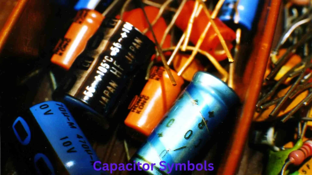
Capacitors store electrical energy temporarily.
Non-Polarized Capacitor
Can be connected in either direction.
Applications
- Filters
- Timing circuits
- Signal processing
Polarized Capacitor
Must be connected correctly.
Common Uses
- Power supplies
- Electronic devices
- Audio systems
Inductor Symbols
Inductors store energy in magnetic fields.
Applications
- Transformers
- Filters
- Radio systems
- Communication devices
Inductors are essential components in modern electronics.
Transformer Symbols
Transformers change voltage levels.
Functions
- Step-up voltage
- Step-down voltage
- Electrical isolation
Real-Life Examples
- Phone chargers
- Power stations
- Industrial equipment
Lamp and Lighting Symbols
Lamp Symbol
Represents a light source.
Applications
- Home lighting
- Automotive systems
- Industrial indicators
LED Symbol
LED stands for Light Emitting Diode.
Benefits
- Energy efficiency
- Long lifespan
- Bright illumination
LED symbols appear in modern electronics and lighting diagrams.
Motor Symbols
Motors convert electrical energy into mechanical motion.
Common Uses
- Fans
- Pumps
- Elevators
- Manufacturing equipment
Motor symbols are frequently found in industrial wiring diagrams.
Relay Symbols
A relay is an electrically controlled switch.
Applications
- Automation systems
- Vehicles
- Security systems
- Industrial controls
Why Relays Matter
Relays allow low-power signals to control high-power devices safely.
Diode Symbols
Diodes control current direction.
Function
Allow electricity to flow one way only.
Examples
- Power supplies
- Chargers
- Electronic circuits
Zener Diode
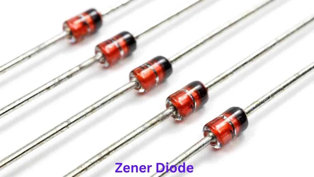
Specialized diode used for voltage regulation.
Applications
- Power protection
- Voltage stabilization
- Electronic regulation
Transistor Symbols
Transistors are among the most important components in electronics.
Functions
- Amplification
- Switching
- Signal control
Modern computers contain billions of transistors.
Common Wiring Diagram Symbols Table
| Symbol Category | Function |
| Wire | Carries current |
| Battery | Provides power |
| Switch | Controls current |
| Fuse | Protects circuits |
| Resistor | Limits current |
| Capacitor | Stores charge |
| Inductor | Stores magnetic energy |
| Transformer | Changes voltage |
| Motor | Produces motion |
| Relay | Controls circuits |
| Diode | Directs current |
| Ground | Safety connection |
How to Read Wiring Diagram Symbols
Reading a wiring diagram becomes easier when you follow a step-by-step process.
Step 1: Identify the Power Source
Locate the battery or AC supply.
Step 2: Follow the Wires
Trace electrical pathways.
Step 3: Recognize Components
Identify switches, motors, relays, and protection devices.
Step 4: Understand Current Flow
Observe how electricity travels through the circuit.
Step 5: Analyze Control Logic
Determine how switches and controls affect operation.
Practical Applications of Wiring Diagram Symbols
Wiring diagram symbols are used in countless industries.
Residential Electrical Systems
Electricians use symbols when installing:
- Lighting systems
- Outlets
- Circuit breakers
- Smart home devices
Automotive Industry
Vehicle wiring diagrams contain symbols for:
- Batteries
- Sensors
- Ignition systems
- Lighting circuits
Mechanics rely heavily on these diagrams.
Industrial Manufacturing
Factories use wiring diagrams for:
- Motor controls
- Automation equipment
- Robotics
- Safety systems
Renewable Energy Systems
Solar and wind power installations use symbols to represent:
- Solar panels
- Batteries
- Inverters
- Charge controllers
Electronics Design
Engineers create schematics using symbols before building actual circuits.
This reduces design errors and improves efficiency.
Common Mistakes Beginners Make
Learning wiring diagram symbols takes practice.
Mistake 1: Ignoring Ground Symbols
Ground connections are critical for safety.
Mistake 2: Confusing AC and DC Symbols
Different power sources require different handling.
Mistake 3: Misreading Wire Connections
Not every crossing wire is connected.
Mistake 4: Overlooking Component Ratings
Symbols show function, but specifications still matter.
Benefits of Understanding Wiring Diagram Symbols
Learning wiring diagram symbols provides many advantages.
Improved Safety
Understanding diagrams reduces wiring errors.
Better Troubleshooting
Problems can be diagnosed more quickly.
Career Opportunities
Electrical skills are valuable in many industries.
Cost Savings
Correct installations reduce repair expenses.
Educational Growth
Students gain a stronger understanding of electrical principles.
Interesting Facts About Wiring Diagram Symbols
- Electrical symbols are recognized worldwide.
- Modern aircraft contain thousands of wiring diagrams.
- Engineers often create digital schematics before construction begins.
- Circuit diagrams helped power the technological revolution.
- Some industrial control diagrams contain hundreds of symbols on a single page.
Impact of Wiring Diagram Symbols on Society
Although often overlooked, wiring diagram symbols have transformed modern life.
Without standardized symbols:
- Buildings would be harder to construct.
- Electrical systems would be less safe.
- Electronics manufacturing would slow dramatically.
- Global engineering collaboration would become difficult.
These symbols help power everything from hospitals and transportation systems to smartphones and renewable energy projects.
Future of Wiring Diagram Symbols
As technology evolves, wiring diagrams continue to adapt.
Emerging areas include:
- Smart homes
- Electric vehicles
- Artificial intelligence systems
- Industrial automation
- Renewable energy networks
New symbols may appear, but the need for clear electrical communication will remain essential.
Frequently Asked Questions
1. What are wiring diagram symbols?
Wiring diagram symbols are standardized graphical representations of electrical components used in circuit and wiring diagrams.
2. Why are wiring diagram symbols important?
They help electricians, engineers, and technicians understand electrical systems quickly and accurately.
3. Are wiring diagram symbols universal?
Most symbols follow international standards, although minor differences exist between regions and organizations.
4. What is the most common wiring diagram symbol?
The wire symbol is the most frequently used because every electrical circuit requires conductors.
5. Can beginners learn wiring diagram symbols easily?
Yes. With practice and familiarity, most people can learn the basic symbols and understand simple wiring diagrams.
Conclusion
Wiring diagram symbols are the foundation of electrical communication. They allow engineers, electricians, technicians, students, and hobbyists to understand complex systems using a simple visual language.
From batteries and switches to motors and transformers, every symbol plays an important role in showing how electricity flows through a circuit.
As our world becomes increasingly dependent on technology, the ability to read and understand wiring diagram symbols becomes even more valuable.
Whether you’re working on a home project, studying electronics, repairing a vehicle, or pursuing a career in engineering, mastering these symbols opens the door to a deeper understanding of electrical systems and modern technology.

Clara Miles
Hello! I’m Clara, a lifelong dreamer who finds magic in everyday moments. Writing has always been my way of exploring the world and understanding the people around me. I love creating stories that make readers laugh, cry, and reflect on life’s little surprises. When I’m not writing, you can usually find me sipping coffee at a cozy café or wandering through nature with a notebook in hand. My journey as an author is fueled by curiosity, imagination, and a love for connecting with my readers. Every story I write is a piece of my heart, and I hope it inspires yours too.
Books:
-
Whispers of the Heart
-
Shadows and Sunlight